Attempting to fix an Olivetti M24
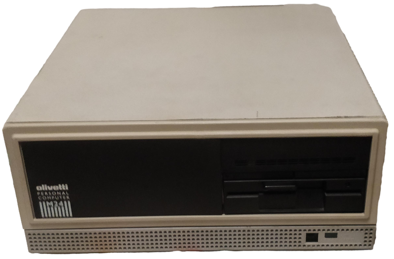
I recently came into possession of an Olivetti M24, a PC-compatible computer from the 80s. It’s a pretty cool machine from the time, featuring the venerable Intel 8086 CPU, a hard drive of unknown capacity, and a 5.25” floppy disk drive.
I just gave it away to a friend who’s got more free time than me and only after giving it did I realize that it would maybe make an interesting low-effort blog post. So here we are.
 Low-quality photo of the computer taken with my old phone in low light conditions
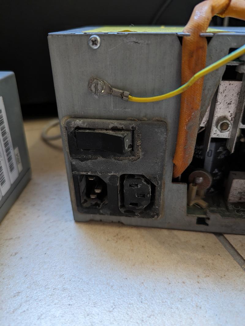
I quite stupidly tried to turn it on without cleaning it beforehand, but as expected it didn’t work at all. The power supply fan did start spinning though, which was to me the first reminder of the olden days whence this beast came: the fan is actually wired directly to the power supply’s input… in other words, a small 12-13cm fan is running on 220V AC. That was something to behold.
After that, I started over and opened it up, and cleaned it thoroughly. There was quite a bit of dust from the years it had spent unused in an attic, but nothing that my compressed air couldn’t handle. I forgot to take pictures at that point so you’ll have to take my word for it.
I first checked whether the power supply worked at all – remember, the fan worked, but not thanks to the supply, so I had to check the real output rails ; lo and behold, nothing. Neither the 12V nor the 5V rails worked, which is not really surprising for a power supply that old. I quickly swapped it for an ATX power supply I keep around for these kind of needs, and it… didn’t work. Not in an expected way, though: there was a short-circuit somewhere since my lab power supply turned itself off as soon as I plugged it to the motherboard’s 5V rail, indicating low resistance between the two contacts.
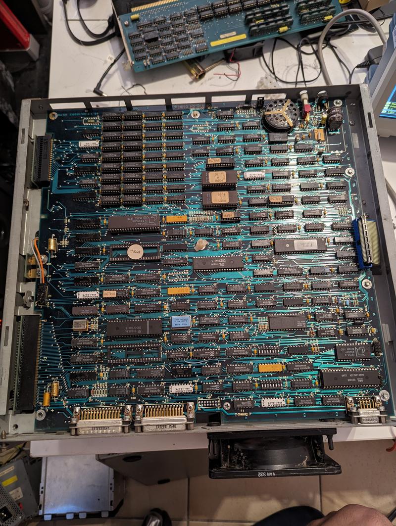
Here’s the motherboard in all its glory. It’s a pretty standard AT motherboard, with a few interesting things to note:
- what you’re seeing here is actually on the bottom of the computer, there is a daughter board on the other side (facing up) that has all the ISA extension ports
- pretty much everything is socketed, which means pretty much everything can be replaced — compare that to the soldered RAM chips we find on many computers nowadays
Here’s a close up of some important chips. Top to bottom, we can see:
- an empty socket for an 8087 math coprocessor
For those with us who haven’t had the pleasure of building a PC in those days, most consumer CPUs back then didn’t have support for floating-point operations out of the box. These features were emulated in software, which worked but was slow, but there was still the option of using a dedicated chip like the 8087. All the FP computations would be offloaded to it and you’d get a nice speed boost. The way it worked was quite interesting: the 8087 was directly wired to the 8086’s address and data buses, and would just sit around doing nothing until an FP instruction would get caught by the 8086, which would pause itself while the 8087 would wake up and process it, eventually yielding the control back to the 8086. Later CPUs (80486 and onwards) would have FP support built-in, and the 8087 instructions became part of the main x86 instruction set.
the 8086 CPU, in particular the AMD D8086-1, which is a slight upgrade from the original one with a frequency of 10 MHz (more info here)
18 NEC D4164C-3 64Kx1 (that’s 64 kb, kilobits, so 8 kilobytes) DRAM chips, for a total of 144 KB
18 TI TMS4164-15NL 64Kx1 DRAM chips, for a total of 144 KB
So, 288 KB total RAM on-board. Not a lot for our modern standards, but still 72 times what it took to land on the moon, and in any case DOS wouldn’t allow you to address more than 640K (which ought to be enough for anybody).
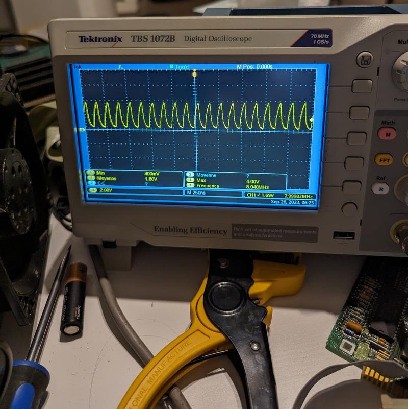
I noticed something weird, though: the computer would turn on and stay on (without shutting my power supply off) if… I put an ammeter in series with the 5V rail. I don’t know why, but it worked. Probably magic. Well, to be fair, it didn’t “turn on”, nothing came out of the display port and nothing seemed to happen in the CPU buses, but the clock seemed to be running? Here’s the CPU clock pin measured by my (admittedly 70MHz) scope:
As to why the signal is 8 MHz instead of the CPU’s rated 10, I have no idea. This is not a “how I fixed an old PC” blog post, this is a “how I tried making an old PC work by poking it around with a stick” blog post.
This is another pic of me trying to make it work, this time measuring with a different oscilloscope. Same result (125.7 ns period so pretty much 8 MHz):
I also tried jerry-rigging a VGA adapter for the proprietary Olivetti video output port (thanks to these amazing resources [1] [2]), but couldn’t get anything out of it. There seemed to be a horizontal blanking signal, but I was unable to measure the vertical one. I think many things were broken. I’m not convinced my 21st-century flatscreen monitor would have been able to display a 320x200 signal anyway.
I ended up giving up and using my analog oscilloscope for better things:
-800.jpg)


-800-3954c1889.jpg)

-800-a8d17d0eb.jpg)